
No products
Prices are tax excluded
Product successfully added to your shopping cart
There are 0 items in your cart. There is 1 item in your cart.
 View larger

Tri-Bar
New
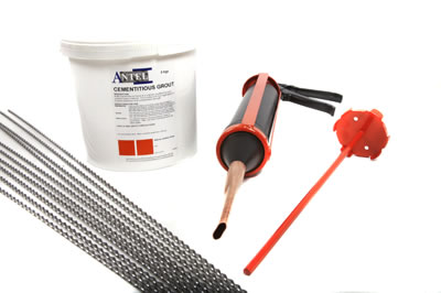
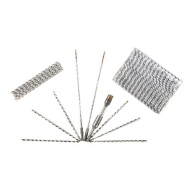
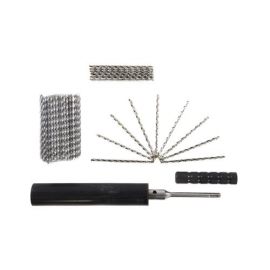
We offer two fantastic value crack stitching kits:
Starter Crack Stitching Kit (£44)
- 5 X 6mm x 1 Metre Tri-Bar
- 5 X 300ml Triset Polyester Resin (fits a standard mastic gun)
Crack Stitching Repair Kit (£84)
- 10 X 6mm x 1 Metre Tri-Bar
- 3 Litre Cementitious Grout
- Pointing Gun & Nozzle
- Mixing Paddle
To purchase either of the kits please click on the dropdown menu below to add them to your basket.
Please view the 'Quantity Discounts' tab below to see our pricing for larger orders.
Volume discounts
| Quantity | Price | You Save |
|---|---|---|
| 500 | £ 2.56 | Up to £ 320.00 |
| 100 | £ 2.88 | Up to £ 32.00 |
| 50 | £ 3.04 | Up to £ 8.00 |
- More info
- Quantity Discounts
- Steel Properties
- Repair Strategies
- Triset Resin
- Cem-Spand
- PDF Download
- Related Posts
Tri-Bar
Why Tri-bar? Tri-bars are three finned helical Stainless Steel reinforcement rods, which can be used in accordance with (BS 5628 part 2) for reinforcing bed-joints to enhance lateral loading resistance in new and existing buildings. Tri-bars can also be used to repair many structural defects in existing masonry by using our repair strategies like over-pinning with ring beams, general crack stitching repairs and lintel failures.
Benefits & Features:
- Quick installation.
- Low labour Costs.
- Easily installed in bed joints.
- Minor visual and structual disturbance.
- Enhances lateral loading resistance .
- Lengths up to 7 metres.
- Austenitic 304 or 316 stainless steel.
- Bonded with Tri-Set resin or cemspand grout.
- Effective in cavity and solid walls.
- Tensile strength more than double required by BS 5628.
- Good bonding to resins and grouts.
Crack stitching:
Re-stabilising existing masonry above failed lintels:
Ring beams to improve lateral load resistance and over pinning to reduce the under pinning cost:
Reinforcing mortar beds to enhance lateral loading resistance in new construction:
| Size | Buy 50+ | Buy 100+ | Buy 500+ |
| Tri-Bar 6.0mm x 1 Metre | £3.04 | £2.88 | £2.56 |
| Tri-Bar 6.0mm x 1.5 Metres |
£4.56 | £4.32 | £3.84 |
| Tri-Bar 6.0mm x 2 Metres | £6.08 | £5.76 | £5.12 |
| Tri-Bar 6.0mm x 2.5 Metres | £7.60 | £7.20 | £6.40 |
| Tri-Bar 6.0mm x 3 Metres | £9.12 | £8.64 | £7.68 |
| Tri-Bar 6.0mm x 3.5 Metres | £10.64 | £10.08 | £8.96 |
| Tri-Bar 6.0mm x 4 Metres | £12.16 | £11.52 | £10.24 |
| Tri-Bar 6.0mm x 4.5 Metres | £13.68 | £12.96 | £11.52 |
| Tri-Bar 6.0mm x 5 Metres | £15.20 | £14.40 | £12.80 |
| Tri-Bar 6.0mm x 5.5 Metres | £16.72 | £15.84 | £14.08 |
| Tri-Bar 6.0mm x 6 Metres | £18.24 | £17.28 | £15.36 |
| Tri-Bar 6.0mm x 6.5 Metres | £19.76 | £18.72 | £16.64 |
| Tri-Bar 6.0mm x 7 Metres | £21.28 | £20.16 | £17.92 |
| Tri-Bar 8.0mm x 1 Metre | £3.99 | £3.78 | £3.36 |
| Tri-Bar 8.0mm x 1.5 Metre | £5.99 | £5.67 | £5.04 |
| Tri-Bar 8.0mm x 2.0 Metre | £7.98 | £7.56 | £6.72 |
| Tri-Bar 8.0mm x 2.5 Metre | £9.98 | £9.45 | £8.40 |
| Tri-Bar 8.0mm x 3 Metre | £11.97 | £11.34 | £10.08 |
| Tri-Bar 8.0mm x 3.5 Metre | £13.97 | £13.23 | £11.76 |
| Tri-Bar 8.0mm x 4 Metre | £15.96 | £15.12 | £13.44 |
| Tri-Bar 8.0mm x 4.5 Metre | £17.96 | £17.01 | £15.12 |
| Tri-Bar 8.0mm x 5 Metre | £19.95 | £18.90 | £16.80 |
| Tri-Bar 8.0mm x 5.5 Metre | £21.95 | £20.79 | £18.48 |
| Tri-Bar 8.0mm x 6 Metre | £23.94 | £22.68 | £20.16 |
| Tri-Bar 8.0mm x 6.5 Metre | £25.94 | £24.57 | £21.84 |
| Tri-Bar 8.0mm x 7 Metre | £27.93 | £26.46 | £23.52 |
Chemical Composition, Mechanical & Design Properties for product profiles used in the manufacture of Tri-bars, Ties and Fixings.
Chemical Composition
|
Austenitic Steel |
C
% |
Si
% |
Mn
% |
P
% |
S
% |
Cr
% |
Mo
% |
Ni
% |
|
304.S15 |
0.06 |
1.0 |
2.0 |
0.045 |
0.030 |
17.5-19.0 |
- |
8.0-11.0 |
|
316.S31 |
0.07 |
1.0 |
2.0 |
0.045 |
0.030 |
16.5-18 .5 |
2.00-2.50 |
10.5-13.5 |
Mechanical Properties
| Size Dia
mm |
0.1%PS
N/mmsq |
0.2%PS
N/mmsq |
1%PS
N/mmsq |
2%PS
N/mmsq |
UTS %
N/mmsq |
ELONg
ON 50mm |
| 4.5 | 813.1 | 911.8 | 1205.0 | 1276.3 | 1284.9 | 5.18 |
| 6.0 | 698.7 | 803.4 | 1015.1 | 1132.1 | 1155.38 | 7.37 |
| 8.0 | 707.9 | 814.0 | 1065.0 | 1147.1 | 1170.6 | 7.28 |
Design features
| Size Dia
mm |
Cross Section
Area mm2 |
Pitch of Helix mm | Angle of Helix Degrees | CoreDiameter
mm |
Number of
Finns |
Length of Finns
mm |
Radius of Finn end
mm |
| 4.5 | 5.250 | 10 | 25 | 1.5 | 3 | 1.5 | 0.35 |
| 6.0 | 8.806 | 13 | 25 | 1.8 | 3 | 2.5 | 0.35 |
| 8.0 | 10.913 | 17 | 25 | 1.95 | 3 | 3.0 | 0.35 |
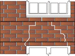
TB-01 - General Crack Stitching
TB-01b - Crack Stitching Solid Walls
TB-02 - Repairing Failed Lintels in Solid Walls
TB-03 - Repairing Failed Lintels in Cavity Walls
TB-03b - Repairing Failed Lintels in Cavity Walls Using Resin Anchors
TB-04 - Repairing Failed Angle Iron Lintels in Cavity Walls
TB-05 - Reconnect of Internal Walls with Solid External Walls
TB-06 - Reconnect of Internal Walls with Cavity External Walls
TB-07 - Repairing Cracks with Tri-Bar Near Corners of Solid Walls
TB-08 - Repairing Cracks with Tri-Bar Near Corners of Cavity Walls
TB-09 - Installing Reinforcement Beams in Cavity Walls
TB-10 - Installing Reinforcement Beams in Solid Walls
TB-11 - Installing Movement Joints in Solid Walls
TB-12 - Installing Movement Joints in Cavity Walls
TB-13 - Repairing Cracks at Junction of Solid and Cavity Walls
TB-14 - Bay Window Repair, Crack Confined to Junction
TB-15 - Bay Window Repair, Cracks in Various Places Around Bay
TB-16 - Bay Window Repair, Cracks In Various Places Around Bay, Brickwork in Poor Condition
TB-17 - Repairing Brick Arch Structures, Brick Arch Reinforcement
TB-18 - Repairing Brick Arch Structures, Beam End Fixing
TB-19 - Repairing Brick Arch Structures, Brick Arch Reinforcement
TB-20 - Reconnect Internal Corners of Solid Walls
TB-21 - Reconnect Internal Corners in Cavity Walls
TB-22 - Repairing Cracks at Junction of Untied Solid Walls
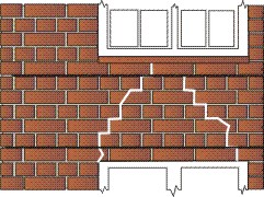
TB-01 - General Crack Stitching
To download a technical data sheet on this repair strategy, please click here...
(1) Cut out slots into horizontal mortar joint to specified depth and at required vertical
spacing.
(2) Blow out slots and thoroughly flush with water.
(3) With the aid of a grout gun insert a 10mm bead of Cemspand cementitious grout or Tri-set resin into the back of the slot.
(4) Push the Tri-bar rod into the grout until a good coverage is achieved.
(5) Insert a second 10mm bead of Cemspand cementitious grout over the exposed
rod and iron into slot using a finger trowel.
(6) When Cemspand has set repoint joint to match existing mortar joint.
Installation Notes: Unless specified otherwise the following criteria are to be used
a) The depth of slot to be 25 to 35mm
b) Normal vertical spacing of crack stitches is 450mm(6 brick courses).
c) Tri-bars are to extend a minimum of 500 mm each side of crack.
d) Where a crack is within 500mm of the end of a wall ( as shown by A above) the Tri-bar is to be continued for at least 100mm around the corner
e) Where a crack is within 500mm of an opening (as shown by B above) the Tri-bar is to be bent back and fixed into the reveal.
TB-01b - Crack Stitching Solid Walls
To download a technical data sheet on this repair strategy, please click here...
(1) Cut out slots into horizontal mortar joint to specified depth and at required vertical
spacing.
(2) Blow out slots and thoroughly flush with water.
(3) With the aid of a grout gun insert a 10mm bead of Cemspand cementitious grout or Tri-set resin into the back of the slot.
(4) Push the Tri-bar rod into the grout until a good coverage is achieved.
(5) Insert a second 10mm bead of Cemspand cementitious grout or Tri-set over the exposed
rod and iron into slot using a finger trowel.
(6) When Cemspand has set re-point joint to match existing mortar joint.
Installation Notes: Unless specified otherwise the following criteria are to be used
a) The depth of slot to be 55 to 70mm
b) Normal vertical spacing of crack stitches is 450mm(6 brick courses).
c) Tri-bars are to extend a minimum of 500 mm each side of crack.
d) Where a crack is within 500mm of the end of a wall ( as shown by A above)
the Tri-bar is to be continued for at least 100mm around the corner
e) Where a crack is within 500mm of an opening (as shown by B above) the Tri-bar is to be bent back and fixed into the reveal.
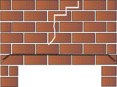
TB-02 - Repairing Failed Lintels in Solid Walls
To download a technical data sheet on this repair strategy, please click here...
(1) Cut out slots into horizontal mortar joints to specified depth and at required vertical spacing.
(2) Blow out slots and thoroughly flush with water.
(3) With the aid of a grout gun insert a 10mm bead of Cemspand cementitious grout or Tri-set resin into the back of the slot.
(4) Push the Tri-bar rod into the grout until a good coverage is achieved.
(5) Insert a second 10mm bead of Cemspand cementitious grout Tri-set resin over the exposed rod.
(6) Push second Tri-bar rod into the grout until a good coverage is achieved.
(7) Insert a third 10mm bead of Cemspand cementitious grout over the exposed
rod and iron into slot using a finger trowel.
(8) When Cemspand has set repoint joint to match existing mortar joint.
Installation Notes: Unless specified otherwise the following criteria are to be used
a) The depth of slot to be 55 to 70mm
b) Tri-bars are to extend a minimum of 500 mm each side of opening.
TB-03 - Repairing Failed Lintels in Cavity Walls
To download a technical data sheet on this repair strategy, please click here...
(1) Cut out slots into horizontal mortar joints to specified depth and at required vertical spacings.
(2) Blow out slots and thoroughly flush with water.
(3) With the aid of a grout gun insert a 10mm bead of Cemspand cementitious grout Tri-set resin into the back of the slots.
(4) Push the Tri-bar rod into the grout until a good coverage is achieved.
(5) Insert a second 10mm bead of Cemspand cementitious grout Tri-set resin over the exposed rod.
(6) Push second Tri-bar rod into the grout until a good coverage is achieved.
(7) Insert a final 10mm bead of Cemspand cementitious grout Tri-set resin over the exposed rod and iron into slot using a finger trowel.
(8) When Cemspand has set re-point joint to match existing mortar joint.
Installation Notes: Unless specified otherwise the following criteria are to be used
a) The depth of slot to be 40 to 55mm
b) Tri-bars are to extend a minimum of 500 mm each side of opening.
TB-03b - Repairing Failed Lintels in Cavity Walls Using Resin Anchors
To download a technical data sheet on this repair strategy, please click here...
(1) Cut out slots into horizontal mortar joints to specified depth and at required vertical spacings, continue slots has far as possible.
(2) Blow out slots and thoroughly flush with water.
(3) Where slots end, drill 14 mm hole into the wall as shown.
(4) Blow out hole to remove dust debris.
(5) Cut Tri-bar’s to required length and bend the end to suit hole and slot
(6) With the aid of a grout gun insert a 10mm bead of Cemspand cementitious grout into
the back of the slot.
(7) Fill hole with Tri- set resin push Tri-bar rods into the resin and grout until a good coverage is achieved.
(8) Insert a second 10mm bead of Cemspand cementitious grout over the exposed rod.
(9) Push second Tri-bar rod into the resin and grout until a good coverage is achieved.
(10) Insert a final 10mm bead of Cemspand cementitious grout over the exposed
rod and iron into slot using a finger trowel.
(11) When Cemspand has set replaster joints.
Installation Notes: Unless specified otherwise the following criteria are to be used.
a) The depth of slot to be 55 to 70 mm (not including plaster).
b) Normal vertical spacing of internal crack stitching is 450mm and Tri-bars to
extend 500mm beyond any cranks in the internal wall.
c) depth of holes to be 100mm
TB-04 - Repairing Failed Angle Iron Lintels in Cavity Walls
To download a technical data sheet on this repair strategy, please click here...
(1) Cut out slots into horizontal and perp mortar joints to specified depth and at
required vertical spacings.
(2) Blow out slots and thoroughly flush with water.
(3) With the aid of a grout gun insert a 10mm bead of Cemspand cementitious grout
into the back of the slots.
(4) Push the Perp anchors and then Tri-bar rod into the grout until a good coverage is
achieved.
(5) Insert a second 10mm bead of Cemspand cementitious grout over the exposed
rods and anchors.
(6) Push second row of Perp anchors and Tri-bar rods into the grout until a good
coverage is achieved.
(7) Insert a final 10mm bead of Cemspand cementitious grout over the exposed
rods and iron into slot using a finger trowel.
(8) When Cemspand has set remove bricks A to allow removal of laminated angle
Lintel, then re-bed bricks A and repoint joints to match existing mortar joint.
Installation Notes: Unless specified otherwise the following criteria are to be used
a) The depth of slot to be 40 to 55mm
b) Perp anchors to be fitted to all perps spaning lintel
c) Tri-bars are to extend a minimum of 500 mm each side of opening.
TB-05 - Reconnect of Internal Walls with Solid External Walls
To download a technical data sheet on this repair strategy, please click here...
(1) Cut out slots into horizontal mortar joints to specified depth and at required vertical spacings, continue slots into corner.
(2) Blow out slots and thoroughly flush with water.
(3) Where slots meet an internal corner, drill 10 mm hole into the adjoining wall as
shown.
(4) Blow out hole to remove dust debris.
(5) Cut Tri-bar to required length and bend the end to suit hole and slot
(6) With the aid of a grout gun insert a 10mm bead of Cemspand cementitious grout into the back of the slot.
(7) Fill hole with Tri- set resin push Tri-bar rod into the resin and grout until a good
coverage is achieved.
(8) Insert a final 10mm bead of Cemspand cementitious grout over the exposed rod and iron into slot using a finger trowel.
(8) When Cemspand has set replaster joints.
Installation Notes: Unless specified otherwise the following criteria are to be used.
a) The depth of slot to be 25 to 35mm (not including plaster).
b) Normal vertical spacing of internal crack stitching is 450mm and Tri-bars to
extend 500mm beyond any cranks in the internal wall
TB-06 - Reconnect of Internal Walls with Cavity External Walls
To download a technical data sheet on this repair strategy, please click here...
(1) Cut out slots into horizontal mortar joints to specified depth and at required vertical spacings, continue slots into corner.
(2) Blow out slots and thoroughly flush with water.
(3) Where slots meet an internal corner, drill 10 mm hole into the adjoining wall as
shown.
(4) Blow out hole to remove dust debris.
(5) Cut Tri-bar to required length and bend the end to suit hole and slot
(6) With the aid of a grout gun insert a 10mm bead of Cemspand cementitious
grout into the back of the slot.
(7) Fill hole with Tri-set resin push Tri-bar rod into the resin and grout until a good
coverage is achieved.
(8) Insert a final 10mm bead of Cemspand cementitious grout over the exposed
rod and iron into slot using a finger trowel.
(8) When Cemspand has set replaster joints.
(9) Tie inner and outer leaves using Tri-fix wall ties.
Installation Notes: Unless specified otherwise the following criteria are to be used.
a) The depth of slot to be 25 to 35mm (not including plaster).
b) Normal vertical spacing of internal crack stitching is 450mm and Tri-bars to extend 500mm beyond any cranks in the internal wall
c) Wall ties to be inserted 225mm either side of junction and staggered vertical
225mm.
TB-07 - Repairing Cracks with Tri-Bar Near Corners of Solid Walls
To download a technical data sheet on this repair strategy, please click here...
(1) Cut out slots into horizontal mortar joints to specified depth and at required vertical spacing.
(2) Blow out slots and thoroughly flush with water.
(3) With the aid of a grout gun insert a 10mm bead of Cemspand cementitious grout
into the back of the slot.
(4) Push the Tri-bar rod into the grout until a good coverage is achieved.
(5) Insert a second 10mm bead of Cemspand cementitious grout over the exposed
rod and iron into slot using a finger trowel.
.
(6) When Cemspand has set repoint joint to match existingt.
Installation Notes: Unless specified otherwise the following criteria are to be used.
a) The depth of slot to be 35mm.
b) Normal vertical spacing of crack stitches is 450mm(6 brick courses).
c) Tri-bars are to extend a minimum of 500 mm each side of crack.
d) Where a crack is within 500mm of the end of a wall the Tri-bar is to be continued
for at least 100mm around the corner.
e) Where a crack is within 500mm of an opening the Tri-bar is to be bent back and
fixed into the reveal.
TB-08 - Repairing Cracks with Tri-Bar Near Corners of Cavity Walls
To download a technical data sheet on this repair strategy, please click here...
(1) Cut out slots into horizontal mortar joints to specified depth and at required vertical spacing.
(2) Blow out slots and thoroughly flush with water.
(3) With the aid of a grout gun insert a 10mm bead of Cemspand cementitious grout
into the back of the slot.
(4) Push the Tri-bar rod into the grout until a good coverage is achieved.
(5) Insert a second 10mm bead of Cemspand cementitious grout over the exposed
rod and iron into slot using a finger trowel.
.
(6) When Cemspand has set repoint joint to match existingt.
Installation Notes: Unless specified otherwise the following criteria are to be used.
a) The depth of slot to be 25mm.
b) Normal vertical spacing of crack stitches is 450mm(6 brick courses).
c) Tri-bars are to extend a minimum of 500 mm each side of crack.
d) Where a crack is within 500mm of the end of a wall the Tri-bar is to be continued
for at least 100mm around the corner.
e) Where a crack is within 500mm of an opening the Tri-bar is to be bent back and
fixed into the reveal.
TB-09 - Installing Reinforcement Beams in Cavity Walls
To download a technical data sheet on this repair strategy, please click here...
(1) Cut out slots into horizontal mortar joints to specified depth and at required vertical spacings.
(2) Blow out slots and thoroughly flush with water.
(3) With the aid of a grout gun insert a 10mm bead of Cemspand cementitious grout
into the back of the slots.
(4) Push the Tri-bar rod into the grout until a good coverage is achieved.
(5) Insert a second 10mm bead of Cemspand cementitious grout over the exposed
rod.
(6) Push second Tri-bar rod into the grout until a good coverage is achieved.
(7) Insert a final 10mm bead of Cemspand cementitious grout over the exposed
rod and iron into slot using a finger trowel.
(8) When Cemspand has set repoint joint to match existing mortar joint.
Installation Notes: Unless specified otherwise the following criteria are to be used
a) The depth of slot to be 40 to 55mm.
b) When joining in long runs of Tri-bars a minimum of 500 mm overlap must be
allowed.
C) Spacing between top and bottom beams should be positioned as far apart
has practicable to a maximum distance of 0.9m (12 brick courses).
TB-10 - Installing Reinforcement Beams in Solid Walls
To download a technical data sheet on this repair strategy, please click here...
(1) Cut out slots into horizontal mortar joints to specified depth and at required vertical spacings.
(2) Blow out slots and thoroughly flush with water.
(3) With the aid of a grout gun insert a 10mm bead of Cemspand cementitious grout
into the back of the slots.
(4) Push the Tri-bar rod into the grout until a good coverage is achieved.
(5) Insert a second 10mm bead of Cemspand cementitious grout over the exposed
rod.
(6) Push second Tri-bar rod into the grout until a good coverage is achieved.
(7) Insert a final 10mm bead of Cemspand cementitious grout over the exposed
rod and iron into slot using a finger trowel.
(8) When Cemspand has set repoint joint to match existing mortar joint.
Installation Notes: Unless specified otherwise the following criteria are to be used
a) The depth of slot to be 55 to 70mm.
b) When joining in long runs of Tri-bars a minimum of 500 mm overlap must be
allowed.
C) Spacing between top and bottom beams should be positioned as far apart
has practicable to a maximum distance of 0.9m (12 brick courses).
TB-11 - Installing Movement Joints in Solid Walls
To download a technical data sheet on this repair strategy, please click here...
(1) Cut out movement joint to specified width and location.
(2) Cut out slots into horizontal mortar joints to specified depth and length on either
side of the movement joint at required vertical spacings.
(3) Blow out slots and insert a bead of Tri-set resin Approx 10mm in depth into the back of the slots.
(4) Slide the plastic tubing over one end of the Tri-bar rod and push the complete
assembly into the resin, make sure that no resin comes into contact with the tri-bar
being sleeved by the tubing.
(5) Insert a second 10mm bead of resin over the Tri-bar and Tubing until a good
coverage is achieved.
(6) When resin has set, repoint slots to match existing mortar joints and seal movement joint with foam and colour matching polysulphides.
Installation Notes: Unless specified otherwise the following criteria are to be used.
a) The depth of slot to be 70mm.
b) Tri-bar and sleeving length to extend 200mm either side of movement joint.
c) Normal vertical spacing of Tri-bar assemblies is 300mm (4 brick courses).
d) Alternate sleeves either side of movement joint.
TB-12 - Installing Movement Joints in Cavity Walls
To download a technical data sheet on this repair strategy, please click here...
(1) Install specified number of wall ties either side of new movement joint position
(2) Cut out movement joint to specified width and location.
(3) Cut out slots into horizontal mortar joints to specified depth and length on either
side of the movement joint at required vertical spacings.
(4) Blow out slots and insert a bead of Tri-set resin Approx 10mm in depth into the back of the slots.
(5) Slide the plastic tubing over one end of the Tri-bar rod and push the complete
assembly into the resin, make sure that no resin comes into contact with the tri-bar
being sleeved by the tubing.
(6) Insert a second 10mm bead of Tri-set resin over the Tri-bar and Tubing until a good coverage is achieved.
(7) When resin has set, repoint slots to match existing mortar joints and seal movement
joint with foam and colour matching polysulphides.
Installation Notes: Unless specified otherwise the following criteria are to be used.
a) The depth of slot to be 70mm.
b) Tri-bar and sleeving length to extend 150mm either side of movement joint.
c) Normal vertical spacing of Tri-bar assemblies is 300mm (4 brick courses).
d) Alternate sleeves either side of movement joint.
e) Vertically stagger wall ties 300mm either side of movement joint, and not more
than 225mm from joint.
TB-13 - Repairing Cracks at Junction of Solid and Cavity Walls
To download a technical data sheet on this repair strategy, please click here...
(1) Cut out slots into horizontal mortar joint to specified depth and at required vertical
spacing.
(2) Blow out slots and thoroughly flush with water.
(3) With the aid of a grout gun insert a 10mm bead of Cemspand cementitious grout
into the back of the slot.
(4) Push the Tri-bar rod into the grout until a good coverage is achieved.
(5) Insert a second 10mm bead of Cemspand cementitious grout over the exposed
rod and iron into slot using a finger trowel.
(6) When Cemspand has set repoint joint to match existing mortar joint.
Installation Notes: Unless specified otherwise the following criteria are to be used
a) The depth of slot to be 35mm.
b) Normal vertical spacing of crack stitches is 300mm(4 brick courses).
c) Tri-bars are to extend a minimum of 500 mm each side of crack.
TB-14 - Bay Window Repair, Crack Confined to Junction
To download a technical data sheet on this repair strategy, please click here...
(1) Cut out horizontal slots to specified depth and at required vertical spacings,
continue slots into bay junction.
(2) Blow out slots and thoroughly flush with water.
(3) Where slots meet an internal corner, drill 10 mm hole into the adjoining wall as
shown.
(4) Blow out hole to remove dust debris.
(5) Cut Tri-bar to required length and bend the end to suit hole and slot.
(6) With the aid of a grout gun insert a 10mm bead of Cemspand cementitious
grout into the back of the slot.
(7) Fill hole with Tri- set resin push Tri-bar rod into the resin and grout until a good
coverage is achieved.
(8) Insert a final 10mm bead of Cemspand cementitious grout over the exposed
rod and iron into slot using a finger trowel.
(9) When Cemspand has set replaster joints.
Installation Notes: Unless specified otherwise the following criteria are to be used.
a) The depth of slot to be 25 to 35mm (not including plaster).
b) Normal vertical spacing of crack stitching is 450mm and Tri-bars to
extend 500mm beyond any cranks in the Bay.
TB-15 - Bay Window Repair, Cracks in Various Places Around Bay
To download a technical data sheet on this repair strategy, please click here...
(1) Cut out horizontal slots to specified depth and at required vertical spacings,
continue slots into bay junction.
(2) Blow out slots and thoroughly flush with water.
(3) Where slots meet an internal corner, drill 10 mm hole into the adjoining wall as
shown.
(4) Blow out hole to remove dust debris.
(5) Cut Tri-bar to required length and bend the end to suit hole and slot.
(6) With the aid of a grout gun insert a 10mm bead of Cemspand cementitious
grout into the back of the slot.
(7) Fill hole with Tri- set resin push Tri-bar rod into the resin and grout until a good
coverage is achieved.
(8) Insert a final 10mm bead of Cemspand cementitious grout over the exposed
rod and iron into slot using a finger trowel.
(9) When Cemspand has set replaster joints.
Installation Notes: Unless specified otherwise the following criteria are to be used.
a) The depth of slot to be 25 to 35mm (not including plaster).
b) Normal vertical spacing of crack stitching is 450mm and Tri-bars to
extend 500mm beyond any cranks in the Bay.
TB-16 - Bay Window Repair, Cracks In Various Places Around Bay, Brickwork in Poor Condition
To download a technical data sheet on this repair strategy, please click here...
(1) Cut out horizontal slots to specified depth and at required vertical spacings,
continue slots into bay junction.
(2) Blow out slots and thoroughly flush with water.
(3) Where slots meets bay junction , drill 10 mm hole into the adjoining wall as
shown.
(4) Blow out hole to remove dust debris.
(5) Cut Tri-bars to required length and bend the bars to suit holes and slot.
(6) With the aid of a grout gun insert a 10mm bead of Cemspand cementitious
grout into the back of the slot.
(7) Fill holes with Tri- set resin push Tri-bar rod into the resin and grout until a good
coverage is achieved.
(8) Insert a second 10mm bead of Cemspand cementitious grout over the exposed
rod.
(9) Push second Tri-bar rod into the resin and grout until a good coverage is achieved.
(10) Insert a final 10mm bead of Cemspand cementitious grout over the exposed
rod and iron into slot using a finger trowel.
(11) When Cemspand has set repoint joints.
Installation Notes: Unless specified otherwise the following criteria are to be used.
a) The depth of slot to be 40 to 55mm.
b) Normal vertical spacing of crack stitching is 450mm, install beams above and
below windows.
c) Run Tri-bars around bay as in TB-09 and insert ends as in TB-06 into main wall
either side of bay
d) Provide additional support to any failed lintels or arches, and Bow-fix into floor and
ceiling timbers
TB-17 - Repairing Brick Arch Structures, Brick Arch Reinforcement
To download a technical data sheet on this repair strategy, please click here...
(1) Cut out slots into underside of arch to specified depth and at required spacings.
(2) Drill clearance holes (12mm-16mm diameter depending upon length of tie to be used) to required depth and required spacing along slots. The holes to be angled at approximately 60 degrees to the right or left of the slots. Alternate holes to go in opposite directions.
(3) Blow out holes and thoroughly flush with water.
(4) With the aid of a grout gun and correct length of nozzle, pump Cemspand cementitious grout until nozzle is full. Insert nozzle to the full depth of drilled hole and pump grout to fill hole. Allow the back pressure to push nozzle out while filling or voids with grout.
(5) Push correct length of Cem-Fix tie into the hole using insertion tool. The end of the tie to be left bent slightly and protruding in slot for Tri-bar reinforcing.
(6) Clean grout away from all protruding ends of Cem-Fix ties and allow 24 hours for grout to achieve an initial set.
(7) After 24 hours blow out slots and thoroughly flush with water.
(8) With the aid of a grout gun insert a 10mm bead of Cemspand cementitious grout into the back of the slot. Push first Tri-bar rod into the grout until a good coverage is achieved.
(9) Insert another 10mm bead of Cemspand cementitious grout over existing Tri-bar and push next Tri-bar rod into the grout until a good coverage is achieved.
(10) Continue to install reinforcements as per (9) above until required number of Tri-bar rods have been installed.
(11) Insert a final 10mm bead of Cemspand cementitious grout over the exposed rod and iron into slot using a finger trowel.
(11) When Cemspand has set repoint joints.
Installation Notes: Unless specified otherwise the following criteria are to be used.
a) The depth of slot to be 65 to 75mm.
b) Number of Tri-Bars per slot to be 4
c) Normal spacing of reinforcement slots to be 450mm,
d) Normal spacing between Cem-Fix ties along slots to be 450mm.
e) When joining runs of Tri-Bar a minimum of 500mm overlap must be allowed and all joints must be staggered
TB-18 - Repairing Brick Arch Structures, Beam End Fixing
To download a technical data sheet on this repair strategy, please click here...
(1) Cut out slots for multi Beams down to start point of arch. Drill clearance holes (12mm-16mm diameter depending upon length of tie to be used) to required depth in line with slot for Tri-Bar 1 (Top) and Tri- Bar 4 (bottom). The holes should be angled upwards and down wards from the line of the reinforcing to give an angle of about 30 degrees between them.
(2) Drill clearance holes (12mm-16mm diameter depending upon length of tie to be used) to required depth outwards from the slot for Tri-Bars 2 and 3 ( central bars). The holes should be angled left and right to give an angle of about 30 degrees between the line of the hole and the line of the reinforcing to be 60 degrees between holes.
(3) Blow out holes and thoroughly flush with water. With the aid of a grout gun and correct length of nozzle, pump Cemspand cementitious grout until nozzle is full. Insert nozzle to the full depth of drilled hole and pump grout to fill hole. Allow the back pressure to push nozzle out while filling or voids with grout. Bend Tri-Bar to correct shape and insert end of tri-bar into full depth of grout filled hole. Install remainder of Tri-Bar around arch as per detail in TB-17.
Installation Notes: Unless specified otherwise the following criteria are to be used.
a) The depth of holes in pier to be 450mm.
TB-19 - Repairing Brick Arch Structures, Brick Arch Reinforcement
To download a technical data sheet on this repair strategy, please click here...
(1) Cut out 10mm wide slots in bed joints to underside of arch to specified depth and at required spacings.
(2) Drill clearance holes (12mm-16mm diameter depending upon length of tie to be used) to required depth at ends of slots.
(3) Blow out holes and thoroughly flush with water.
(4) With the aid of a grout gun and correct length of nozzle, pump Cemspand cementitious grout until nozzle is full. Insert nozzle to the full depth of drilled hole and pump grout to fill hole. Allow the back pressure to push nozzle out while filling or voids with grout
(5) After changing nozzle insert a 10mm bead of Cemspand cementitious grout into the back of the slot.
(6) Bend Tri-bar to correct length and shape and insert end of Tri-bar into full depth of the hole. Then pushremainder of Tri-bar into bead of grout in slot to obtain good coverage.
(7) Insert a final 10mm bead of Cemspand cementitious grout over the exposed rod and iron into slot using a finger trowel.
(8) When Cemspand has set repoint joints.
Installation Notes: Unless specified otherwise the following criteria are to be used.
a) The depth of slot to be 45mm.
b) Normal spacing between Tri-bars to be 450mm.
c) Tri-Bars are to extend a minimum of 500mm either side of the crack. If this is not possible then ends of each Tri-bar to be bent and grouted into the brickwork.
TB-20 - Reconnect Internal Corners of Solid Walls
To download a technical data sheet on this repair strategy, please click here...
(1) Cut out slots into horizontal mortar joints to specified depth and at required vertical spacings, continue slots into corner.
(2) Blow out slots and thoroughly flush with water.
(3) Where slots meet an internal corner, drill 14 mm hole into the wall as shown.
(4) Blow out hole to remove dust debris.
(5) Cut Tri-bar’s to required length and bend the end to suit hole and slot
(6) With the aid of a grout gun insert a 10mm bead of Cemspand cementitious grout into the back of the slot.
(7) Fill hole with Tri- set resin push Tri-bar rods into the resin and grout until a good coverage is achieved.
(8) Insert a second 10mm bead of Cemspand cementitious grout over the exposed rod.
(9) Push second Tri-bar rod into the resin and grout until a good coverage is achieved.
(10) Insert a final 10mm bead of Cemspand cementitious grout over the exposed
rod and iron into slot using a finger trowel.
(11) When Cemspand has set replaster joints.
Installation Notes: Unless specified otherwise the following criteria are to be used.
a) The depth of slot to be 55 to 70 mm (not including plaster).
b) Normal vertical spacing of internal crack stitching is 450mm and Tri-bars to
extend 500mm beyond any cranks in the internal wall.
c) depth of holes to be 150mm
TB-21 - Reconnect Internal Corners in Cavity Walls
To download a technical data sheet on this repair strategy, please click here...
(1) Cut out slots into horizontal mortar joints to specified depth and at required vertical spacings, continue slots into corner.
(2) Blow out slots and thoroughly flush with water.
(3) Where slots meet an internal corner, drill 14 mm hole into the wall as shown.
(4) Blow out hole to remove dust debris.
(5) Cut Tri-bar’s to required length and bend the end to suit hole and slot
(6) With the aid of a grout gun insert a 10mm bead of Cemspand cementitious grout into the back of the slot.
(7) Fill hole with Tri- set resin push Tri-bar rods into the resin and grout until a good coverage is achieved.
(8) Insert a second 10mm bead of Cemspand cementitious grout over the exposed rod.
(9) Push second Tri-bar rod into the resin and grout until a good coverage is achieved.
(10) Insert a final 10mm bead of Cemspand cementitious grout over the exposed
rod and iron into slot using a finger trowel.
(11) When Cemspand has set replaster joints.
Installation Notes: Unless specified otherwise the following criteria are to be used.
a) The depth of slot to be 40 to 45 mm (not including plaster).
b) Normal vertical spacing of internal crack stitching is 450mm and Tri-bars to
extend 500mm beyond any cranks in the internal wall.
c) depth of holes to be 80mm.
TB-22 - Repairing Cracks at Junction of Untied Solid Walls
To download a technical data sheet on this repair strategy, please click here...
(1) Cut out slots into horizontal mortar joint to specified depth and at required vertical
spacing.
(2) Blow out slots and thoroughly flush with water.
(3) With the aid of a grout gun insert a 10mm bead of Cemspand cementitious grout
into the back of the slot.
(4) Push the Tri-bar rod into the grout until a good coverage is achieved.
(5) Insert a second 10mm bead of Cemspand cementitious grout over the exposed
rod and iron into slot using a finger trowel.
(6) When Cemspand has set repoint joint to match existing mortar joint.
Installation Notes: Unless specified otherwise the following criteria are to be used
a) The depth of slot to be 35mm.
b) Normal vertical spacing of crack stitches is 300mm(4 brick courses).
c) Tri-bars are to extend a minimum of 500 mm each side of crack.
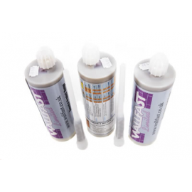
TRISET PRODUCT DATA SHEET
DESCRIPTION
Triset is a rapid curing 'one shot' two part chemical anchoring cartridge system based on a polyester resin. Applied in one single action to produce a cost effective, tough, chemical resistant fixing. Triset is ideal for close-to edge applications (unlike expansion anchors) as no stress is placed on the surrounding substrate. Versatile in use, Triset is suitable for fixing wall ties, starter bars, studs, bolts or large screws in a wide range of substrates including brickwork, concrete, masonry, stone and PFA blocks. Hollow base materials can be securely fastened into by using Triset in conjunction with a sleeve or sieve.
PREPARATION
1. Drill hole to the correct diameter and depth (see chart for guide), ideally using a rotary percussion machine. For optimum results the hole must be coarse sided. If the holes are produced by diamond drilling the surfaces should be thoroughly roughened.
2. Remove all dust and debris from the hole using a hand air pump or a stiff rotary brush.
3. All bars should be clean and free from oil or grease and all flaking rust should be removed. Threaded rod or struts should be chisel-ended to prevent them being unscrewed from the cured resin.
APPLICATION
1. Attach the mixing nozzle to the cartridge (screw down hand tight).
2. Mount the cartridge into the dispensing gun.
3. Squeeze out material through the nozzle until an even colour is achieved (approximately 5-6 inches of extruded material should be adequate).
4. Apply to the hole working from the base out. Once the required fill is obtained release the pressure and wipe away excess material. Place the bolt or screw into the hole with a rotary action. Wipe away excess material. Attach fixture once resin has cured.
NB Once material has started to extrude through the nozzle over pressuring the system will not increase flow rate. And can cause leakage from the rear of the cartridge.
TECHNICAL DATA
MIXING RATIO 10: 1 by volume
Supplied in 380ml cartridges
| TEMPERATURE | GEL TIME | CURE TIME |
| (C) | (F) | (Minutes) | (Minutes) |
| 5 | 41 | 12 | 240 |
| 10 | 50 | 9 | 180 |
| 15 | 59 | 6 | 150 |
| 20 | 68 | 5 | 120 |
| 25 | 77 | 3 | 60 |
ULTIMATE PHYSICAL PROPERTIES
Tensile Strength (ASTM 638) -> 1ON/mm sq.
Compressive Strength (ASTM 695) -> 78N/mm sq.
Flexural Strength (ASTM 790 - 21N/mm sq.
Elastic Modulus - 4570N/mm sq.
Mixed Density - 1.65g/cm sq.
The above physical properties were arrived at independently by Birmingham City Laboratories.
| ANCHOR SIZE | HOLE DIAMETER | HOLE DEPTH | TENSION | FIXINGS PER UNIT |
| (mm) | (mm) | (mm) | (kN) | (Holes Filled 2 Quarters Full) |
| (Ultimate pull out ) |
380ml |
|||
| 8 | 10 | 80 | 23.7 | 90 |
| 10 | 12 | 90 | 25.7 | 56 |
| 12 | 14 | 110 | 43.3 | 34 |
| 16 | 18 | 125 | 53.7 | 18 |
| 20 | 22 | 150 | 58.3 | 10 |
Tension figures quoted are tested in accordance with BS5080 part 1 in 63 N/mm sq concrete blocks (12 x 12 x 12 inches). In all cases for 16mm and 20mm anchors failure of the concrete block was observed before the anchor was dislodged.
The ultimate pull out strength is varied by:
1. The strength of both the substrate and bar/stud
2. The length of the resin bond to bar
3. Hole preparation
4. Anchor separation
Safety factors of between 2:1 and 4:1 should be considered depending on the strength and nature of the substrate. Due to the inconsistent nature of hollow blocks and bricks tension figures may vary. Site testing should be carried out where necessary to establish particular suitability. In order to achieve maximum performance the distance between the centres of the anchors should be a minimum of2.5 x the embedment depth, and 1.25 x the embedment depth for the minimum distance from edges.
STORAGE
Store in a dry area between 5 C and 25 C. Do not expose to direct sunlight. Storage at higher temperatures will reduce the shelf life.
HEALTH AND SAFETY DATA
Triset contains styrene and is flammable. Do not smoke and do not allow naked flames to come into contact with this material. Avoid breathing vapour and wear suitable protective clothing such as gloves and overalls. On contact with skin wash off immediately with plenty of soap and water.
IMPORTANT
The information and data given is based on our own experience, research and testing and is believed to be reliable and accurate. However, as Wallfast Ltd. cannot know the varied uses to which its products may be applied, or the methods of application used, no warranty as to the fitness or suitability of its products is given or implied. It is the users responsibility to determine suitability of use. For further information, please contact our Technical Department.
MATERIAL SAFETY DATA SHEET
1. IDENTIFICATION OF SUBSTANCE/PREPARATION AND COMPANY
Product Name: TRI-SET POLYESTER RESIN
Company: Wallfast Ltd - Portsmouth - PO3 6FH
Chemical Name & Synonyms: Unsaturated Polyester Resin in Styrene.
For Information: 023 92298443 (8.30am - 4.30pm)
In an Emergency: As above
2. COMPOSITION/INFORMATION OF INGREDIENTS
Hazardous Components: Cas Number Percentage
Styrene 100-42-5 30-50 %
3. HAZARDS IDENTIFICATION
Harmful by inhalation. Irritating to eyes and skin. Flammable.
Signs and Symptoms of Exposure (Acute Effects) Irritant to skin, eyes and respiratory tract.
Signs and Symptoms of Exposure (Possible Long Term Effects). Irritant can cause skin disorders with repeated prolonged exposure. Inhalation of vapour can cause nausea and headaches.
4. FIRST AID MEASURES
Summon immediate medical assistance after contact with skin, eyes, inhalation or ingestion.
Eye: Irrigate with clean running water for at least 15 minutes. Seek medical attention.
Skin: Remove from skin with plenty of soap and water. Remove contaminated clothing. If irritation persists, seek medical advice.
Ingestion: Drink plenty of water. Seek medical attention. DO NOT INDUCE
VOMITING.
Inhalation: Move patient to fresh air and allow to rest. If patient is slow to recover or unconscious, obtain medical assistance immediately.
First Aiders should protect themselves from exposure (Refer to Section 8)
5. FIRE FIGHTING MEASURES
Extinguishing Media: CO2/ Foam/ Dry Chemical.
Exposure Hazards: Flammable, sealed containers heated can pressurise leading to explosion. Emits acrid black smoke and irritating fumes when heated to decomposition.
Fire Fighting Equipment: N/A
6. ACCIDENTAL RELEASE MEASURES
Do not discharge into sewers. Dike spilled material with liquid absorbent. Scrape or pump into a suitable container. Wash area with water.
Refer to section 5, 8 and 13 for Protective Measures and Disposal.
7. HANDLING AND STORAGE
Store in a cool, dry and well ventilated area. Store away from direct sunlight.
When handling, suitable protective clothing should be worn. (Refer to section 8)
8. EXPOSURE CONTROLS/PERSONAL PROTECTION
OCCUPATIONAL EXPOSURE LIMITS.
Long Term: 100 ppm (UK)
Short Term: 10 minutes 250ppm (UK)
Respiratory: If forced air extraction is not available in enclosed areas an organic vapour mask will be required, if the occupational exposure limit is exceeded.
Ingestion: Unlikely during normal use.
Skin Protection: Wear gloves at all times.
Eye Protection: Not normally required during normal use. If splashing occurs, goggles should be worn.
9. PHYSICAL/CHEMICAL PROPERTIES
Appearance: Amber fluid.
Odour: Styrene.
Viscosity: 6-8 poise at 25 degrees C.
Specific Gravity: 1.10 g/cm3 (20 degrees C)
Boiling Point/Range: N/A
Meeting Point/Melting Range: N/A
Flash Point: 31 degrees C
Flammability: Flammable.
Auto-Flammability: 490 degrees C
Explosive Properties: Lower limit 1.1% Upper limit 6.1%
Oxidising Properties: None.
Vapour Pressure: 6.52 mb 20 C (styrene)
Evaporation Rate: N/A
Solubility: Insoluble in water. Soluble in solvents
pH: N/A
Partition Coefficient: N/A
Di-Electric Strength: N/A
Additional Information: N/A
10. STABILITY AND REACTIVITY
Stability: Can polymerise (solidify) exothermically if heated, exposed to sunlight or by addition of free radical initiators. Stable under normal conditions.
Materials to Avoid: Reacts vigorously with strong oxidising agents and peroxides.
Hazardous Decomposition: Emits acrid smoke and irritating fumes when heated to decomposition.
Hazardous Polymerisations: Polymerisations in a closed container can give rise to pressure, which may rupture the vessel.
11. TOXICOLOGICAL INFORMATION
Oral: Material is classed as harmful. An oral LD50 in rats of 5g/kg Styrene. LC50 in rats ranges between 2770-6000ppm.
Inhalation: Lung irritant can induce drowsiness and eventual unconsciousness.
Eye: Severe irritant
Skin: Moderate irritant
12. ECOLOGICAL INFORMATION
Do not discharge into drains or the environment.
13. DISPOSAL CONSIDERATIONS
In an uncured state, place in a suitable container and dispose as chemical waste in accordance with local regulations. Small quantities may be reacted with the corresponding amount of activator. Allow curing and dispose as solid waste.
14. TRANSPORT INFORMATION
Supply label: Harmful
Flammable
IMDG Code: 3379 UN No./SI No: 1866
EAC: 3 (Y) Hazard Class: 3
ADR HIN: 30 Packing Group: III
15. REGULATORY INFORMATION
Labelling: Harmful, Flammable.
Risk Phrases (R10) Flammable.
(R20) Harmful by inhalation.
(R36/38) Irritating to skin and eyes.
Safety phrases (S2) Keep out of reach of children.
(S23) Do not breathe vapour.
(S36/37/39) Wear suitable protective Clothing.
Gloves and eye/face protection.
16. OTHER INFORMATION
Our ref: SMJH
Date of Preparation: March 2002
Prepared By: S Mullineaux
The information contained within this document is furnished without warranty of any kind. Users should consider this data only as a supplement of other information gathered by them and make independent determinations of suitability and completeness of information from all sources to ensure proper use and disposal of these materials and the safety of employees customers.
Benefits
- Controlled Expansion
- Controlled Compression Strength
- Thixotropic Grout
- Rapidly Cures and Develops High Compressive Strength
- Clean, Safe and Easy to Use
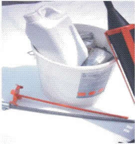
Cem-Spand with Injection Gun
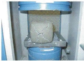
Testing Compression Strength
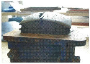
Monitoring Expansion
Compression strength with different amounts of expanding agents per 5 Kgs
| 3 GMS of Expanding Agent | Day 1 | Days 7 | Days 28 |
| Compression strength | 9.9 N/mm2 | 44.0 N/mm2 | 52.0 N/mm2 |
| Expansion | 1% | 1% | 1% |
| Cube Size | 100mm | 100mm | 100mm |
| Cube mass | 1940g | 1876g | 1899g |
| Density | 1940 kg/m3 | 1880 kg/m3 | 1900 kg/m3 |
| Failure Load | 99.1 kN | 442 kN | 522 kN |
| 12 GMS of Expanding Agent | Day 1 | Days 7 | Days 28 |
| Compression strength | 11.0 N/mm2 | 27.5 N/mm2 | 30.5 N/mm2 |
| Expansion | 4% | 4% | 4% |
| Cube Size | 100mm | 100mm | 100mm |
| Cube mass | 1787g | 1775g | 1736g |
| Density | 1790 kg/m3 | 1780 kg/m3 | 1740 kg/m3 |
| Failure Load | 110 kN | 274 kN | 304 kN |
| 25 GMS of Expanding Agent | Day 1 | Days 7 | Days 28 |
| Compression strength | 7.7 N/mm2 | 15.0 N/mm2 | 18.5 N/mm2 |
| Expansion | 16% | 16% | 16% |
| Cube Size | 100mm | 100mm | 100mm |
| Cube mass | 1558g | 1580g | 1560g |
| Density | 1560 kg/m3 | 1580 kg/m3 | 1560 kg/m3 |
| Failure Load | 76.7 kN | 152 kN | 165 kN |
| 50 GMS of Expanding Agent | Day 1 | Days 7 | Days 28 |
| Compression strength | 7.2 N/mm2 | 12.0 N/mm2 | 13.5 N/mm2 |
| Expansion | 20% | 20% | 20% |
| Cube Size | 100mm | 100mm | 100mm |
| Cube mass | 1579g | 1520g | 1580g |
| Density | 1580 kg/m3 | 1520 kg/m3 | 1580kg/m3 |
| Failure Load | 71.9 kN | 119 kN | 133 kN |
| 100 GMS of Expanding Agent | Day 1 | Days 7 | Days 28 |
| Compression strength | 0.7 N/mm2 | 3.7 N/mm2 | 4.9 N/mm2 |
| Expansion | 40% | 40% | 40% |
| Cube Size | 100mm | 100mm | 100mm |
| Cube mass | 1248g | 1258g | 1283g |
| Density | 1250 kg/m3 | 1260 kg/m3 | 1280kg/m3 |
| Failure Load | 7.4 kN | 37.0 kN | 48.7 kN |
To save a file to your computer, right click on the following link and select "save file as..."
Tri-Bar General Information
TB-01 - General Crack Stitching
TB-01b - Crack Stitching Solid Walls
TB-02 - Repairing Failed Lintels in Solid Walls
TB-03 - Repairing Failed Lintels in Cavity Walls
TB-03b - Repairing Failed Lintels in Cavity Walls Using Resin Anchors
TB-04 - Repairing Failed Angle Iron Lintels in Cavity Walls
TB-05 - Reconnect of Internal Walls with Solid External Walls
TB-06 - Reconnect of Internal Walls with Cavity External Walls
TB-07 - Repairing Cracks with Tri-Bar Near Corners of Solid Walls
TB-08 - Repairing Cracks with Tri-Bar Near Corners of Cavity Walls
TB-09 - Installing Reinforcement Beams in Cavity Walls
TB-10 - Installing Reinforcement Beams in Solid Walls
TB-11 - Installing Movement Joints in Solid Walls
TB-12 - Installing Movement Joints in Cavity Walls
TB-13 - Repairing Cracks at Junction of Solid and Cavity Walls
TB-14 - Bay Window Repair, Crack Confined to Junction
TB-15 - Bay Window Repair, Cracks in Various Places Around Bay
TB-16 - Bay Window Repair, Cracks In Various Places Around Bay, Brickwork in Poor Condition
TB-17 - Repairing Brick Arch Structures, Brick Arch Reinforcement
TB-18 - Repairing Brick Arch Structures, Beam End Fixing
TB-19 - Repairing Brick Arch Structures, Brick Arch Reinforcement
TB-20 - Reconnect Internal Corners of Solid Walls
TB-21 - Reconnect Internal Corners in Cavity Walls
TB-22 - Repairing Cracks at Junction of Untied Solid Walls
Viewed products
-

Tri-Bar
Helical Steel Reinforcement Rods,...


Store Information
